How to Size Battery?
Introduction:
The battery storage system is having primary importance in insuring the satisfactory operation of generation station, substation, and other stationary applications. Batteries are the lifeline of the substation. Substations are a part of every power grid. They convert voltage from high to low, and vice versa. Without substations, power grids around the world could not operate. Now, why do substations need batteries? Batteries ensure all critical substation loads will always operate. In a substation, the primary source of power comes from your AC power supply. But you cannot completely rely on your AC power supply. You’ll lose power if a substation, transmission line, or generation source goes offline. So, the battery is an alternate DC power source in case we lose the AC power source to feed the critical loads such as protection relays, circuit breakers, etc.
Why Is Battery Sizing Essential?
Battery sizing is crucial to ascertain that it can supply power to the connected loads for the time it is designed. Unsuitable sizing of the battery can pose many serious problems such as permanent battery damage because of over-discharge, low voltages to the load, and insufficient backup times.
The battery sizing calculations can be initiated once we have the following Data:
- Loads need to be supported by a battery
- Minimal voltage for the battery
- Back up time(s)
Calculation Approach
The calculations performed are based on “Recommended Practice for Sizing Lead-Acid Batteries for Stationary Applications” and “Recommended Practice for Sizing Nickel-Cadmium Batteries for Stationary Applications” IEEE standards. All the calculations in this article are established on conventional lead-acid or nickel-cadmium (NiCd) batteries.
The methodological analysis has five steps as follows:
Step 1: Collect the total connected loads that the battery needs to supply
Step 2: Develop a load profile and further compute design energy
Step 3: Choose the type of battery and determine the cell characteristics
Step 4: Choose the battery cells required to be linked in a series fashion
Step 5: Based on design loads, compute the desired Ampere-hour (Ah) battery capacity
Apart from the above steps following factors must consider before proceeding to calculate the cell size required for a particular installation. These factors always influence cell size.
- Maximum Depth of Discharge
Depth of discharge (DoD) is the fraction or percentage of the capacity which has been removed from the fully charged battery. It is an alternative method to indicate a battery’s state of charge (SoC). The depth of discharge is the complement of the state of charge as one increases, the other decreases.
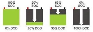
Fig.1. Relation Between DoD and SoC
- Temperature Correction Factor
The battery cells capacity is generally provided for a standardized temperature which is 250C and if it varies somewhere with the installation temperature, a correction factor is needed to implement.
- Design Margin
It is prudent to design practices to provide capacity margin to allow for unforeseen additions to the DC systems and less than optimum operating conditions of the battery due to improper maintenance, recent discharge, ambient temperature lower than anticipated, or a combination of these factors. A method of providing this design margin is to add a percentage factor to the cell size determined by calculations. If the various loads are expected to grow at different rates, it may be more accurate to apply the expected growth at different rates, it may be more accurate to apply the expected growth rate to each load for a given time and to develop a duty cycle from the results.
- Aging Factor
Capacity decreases gradually during the life of the battery, with no sudden capacity loss being encountered under normal operating conditions. Since the rate of capacity loss is encountered under normal operating conditions. Since the rate of capacity loss is dependent upon factors such as operating temperature, electrolyte-specific gravity, depth, and frequency of discharge. The aging factor is chosen based on the required service life.
- Capacity Rating Factor (Kt)
The capacity rating factor KT is the ratio of rated ampere-hour capacity (at a standard time rate, at 250C, and to a standard end of discharge voltage) of a cell, to the amperes that can be supplied by that cell for t minutes at 250C and to a given end of discharge voltage.
KT factors value should be provided by the reference battery manufacturer.
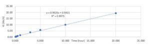
Fig.2. Relation between time and KT factor
KT = Period (Hour) x Gradient + Intercept.
- Section Capacity
Capacity determines for each section is the section capacity. Section capacity is equal to the change in load scaled by the capacity rating factor for the specific section. The total section capacity is equal to the sum of all the section capacities.
Section Capacity = Change in load x KT
Example Of Battery Sizing Calculations
Scope of Work:
For one of our clients, we did the battery sizing calculations for their facilities as per the following scope of work.
The performance of batteries must comply with the following requirements:
- Maintain nominal outage voltage for a minimum of four hours without primary AC supply
- Within these four hours of standby time, the batteries must have sufficient capacity to complete the full operation of the installation for a minimum of two times
- At the end of the four hours of standby time, the batteries must have sufficient capacity to complete a minimum of the consecutive trip, consecutive close operations, and spring charging of 50% of the circuit breakers of the installation
- At the completion of the above operation steps, the final terminal voltage of the batteries must be greater than 85% of the nominal output voltage
System Parameters:
The following are the system specifications considered during the battery sizing calculation and the load profile calculation.
Nominal Voltage (V) – 48
Voltage Fluctuation – 10%
Max DoD – 85%
Final System Voltage (V) – Nominal Voltage x Max DoD – 40.8
Design Margin – 20%
Average Temperature (0C) – 25
Aging Factor – 1.25
System Efficiency – 97%
Calculations:
From the given scope of work, system parameters, load data provided by the client, standard requirements and by considering all calculation approaches calculations performed are as shown in the below table.
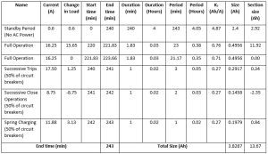
Table – Battery Sizing Calculation Worksheet
From the above worksheet, the battery size required is 13.67Ah. But this is the uncorrected size because correction factors are not applied to the calculations.
Therefore, the final battery size is calculated by considering all the correction factors.
Final Size = [Uncorrected Size x (1+Design Margin) x Aging Factor x Temperature Correction factor] / System Efficiency
= [13.67 x (1+20%) x 1.25 x 10³%] / 97%
= 21.7Ah
Total Battery Capacity = Final Size x Nominal System Voltage / 1000
= 21.7x 48 /1000
= 1.04 kWh
From the above calculations, the battery capacity required for the application is 21.7Ah. The next available standard size of the battery is 24Ah.
Recommendation:
Therefore, recommended battery size is 48V,24Ah to meet the requirement.