The important parameters to consider while selecting power cables for installation are.
Voltage level
Voltage level needs to be considered.
- Low voltage cable (0 to 1000V): Low voltage cables are used for industrial power installations in various fields like general industry, public installations, infrastructures, etc.
- Distribution voltage cables (11kV, 22kV): They are used in the distribution of electricity from electrical substations to Distribution transformers.
- Sub Transmission and Transmission voltage cables (33kV, 66kV, and 132kV): They are used to transport electricity from the generating plants to the electrical substations.
Load Current
A Load Current is the nominal current that passes from a power supply to the device or load. The power delivered electrically is the product of voltage and current in the circuit. Hence, the cross-section area of the cable should be sufficient to carry the maximum load current.
Total Load current(I) for 3 phases = kVA/1.732* Line-Line voltage
Short circuit current
The electricity will flow through a ‘short’ route and cause an electrical short circuit. It determines the minimum cross-sectional area of cable required.
Total Load current(I) for 3 phases = kVA/1.732* Line-Line voltage
A= I*T/K
I = Fault Current
T= Fault clearing time
K= Constant depends on cable material (XLPE OR PVC)
A= Cable cross-section area
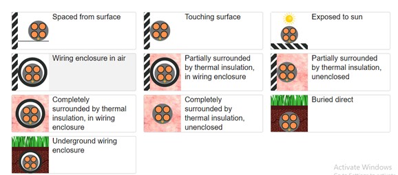
Derating
The derating factor is applied to reduce the cable's current carrying capacity based on the surrounding installation. Derating considers air temperature, soil temperature, cable depth, and Soil resistivity. So, need to upsize the cable to carry the nominal current.
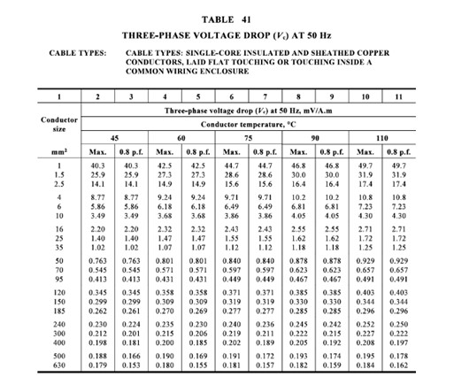
Voltage Drop
It determines the reduction in voltage in an electrical circuit between the source and load. Voltage drop occurs at the load compared to the supply end. The Australian standard allows the voltage to drop by 5%. Generally, power utilities allow a 2.5% voltage drop.
To improve voltage drop upsize the cable or use the copper cable as a better conductor of electricity than Aluminium.
Standards Australia issued AS 60038 in 2000 with 230/400 volts as the nominal voltage with a +10%, -6% range.